Medium-Voltage
reactive power automatic compensation device
Step reactive compensation on 6kV/10kV MV distribution to improve PF, support voltage, and reduce losses, where automatic step compensation delivers the best balance of performance, simplicity, and cost.
- Automatic step switching based on measured reactive power setpoint
- Built around MV capacitor switching vacuum contactors
- Multiple unbalance protection schemes (open-delta / neutral / bridge differential)
Where This Solution Fits Best
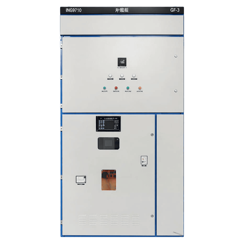
Ideal when you need a cabinetized MV compensation system that improves PF and voltage performance using automatic capacitor step control.
Excess MV Reactive Demand
Your substation records high reactive power on the MV side, reducing available capacity. You need step compensation at the MV bus to unload the upstream supply. Our solution switches capacitor stages automatically to reduce VAR draw.
Limited Transformer Headroom
Reactive current consumes transformer capacity and increases heating. You need to free up kVA and improve operating efficiency without changing loads. Our solution compensates reactive power upstream to lower current and losses.
Frequent Load Step Changes
Plant operations create repeatable load steps that shift PF quickly. You need staged compensation that tracks these changes without constant human intervention. Our solution adds/removes capacitor steps to follow reactive power variation.
How It Works
A system-level approach to power factor correction on 6–10 kV buses
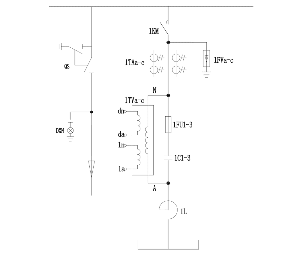
Our soolution is engineered around one priority: deliver steady, repeatable reactive power correction at the MV bus with minimal operator burden. The system combines staged capacitor banks, series reactor design, and capacitor-duty switching hardware under an integrated controller. As reactive demand shifts, the controller automatically selects and switches the required stages to keep compensation within the desired band—supporting voltage stability, reducing reactive losses, and improving substation operating margins.
This step-based control makes it ideal for plants where reactive demand changes in discernible load steps—delivering consistent correction without constant manual tuning.
From Disturbance to Stability: Power Quality Solutions
How We Resolve Power Quality Challenges
Stop Power Factor Drops in Cycles
Whether at a utility feeder or an industrial PCC, PF drifts with load cycles. Our MV compensation approach keeps reactive demand within the target band to meet compliance and reduce penalties.
Stabilize MV Bus Conditions
MV voltage fluctuates as demand shifts across networks and plants. Our solution supports the MV bus voltage profile so downstream feeders and processes see steadier supply conditions.
Reduce Losses and Heating
Reactive current consumes transformer and line capacity and raises thermal stress. By reducing upstream VAR flow, you free usable kVA margin and improve operating security for growth.
Reduce Intervention and Errors
Frequent manual actions increase switching risk and inconsistent outcomes. Our approach minimizes routine intervention so teams focus on operations rather than constant compensation adjustments.
Six Reasons Engineers Choose It
What Makes This Solution Different
Closed-Loop VAR Control
The controller continuously evaluates reactive demand and switches stages to keep compensation within a defined target band. This stabilizes PF and reduces operator dependence across changing load conditions.
Capacitor-Duty Vacuum Switching
Switching is executed by vacuum contactors designed for capacitor-bank duty, improving reliability under frequent operations. This reduces switching risk and keeps stage transitions predictable.
High Current Operating Margin
Supports steady current up to 1.3×In, and up to 1.43×In under defined capacitor/harmonic scenarios. This adds tolerance against harmonic-related stress and loading variation.
High Overcurrent Capability
The system allows steady current up to 1.3×In, and up to 1.43×In under capacitor tolerance and harmonic conditions. This helps maintain stable operation during abnormal but realistic grid scenarios.
Unbalance Protection Options
Protection schemes support open-delta and unbalance-based approaches to detect capacitor-bank abnormalities early. This improves fault discrimination and reduces cascading equipment stress.
Remote Monitoring Ready
Communication readiness (e.g., RS485) supports integration into plant or substation monitoring routines. This enables clearer status visibility and faster maintenance decisions.
Product Models & Standard Configurations
Model Code Rules:
- Switching mode: Z = automatic, D = motor local, blank = manual
- Protection: K = open-delta, C = differential pressure, L = neutral unbalance current
- Wiring: A = single-star, B = double-star
Model | Single-Cabinet Capacity (kvar) | Capacitor Model | Qty | Reactor | Cabinet Size (W×D×H,mm) |
|---|---|---|---|---|---|
INPBB6-300-AK | 300 | UHPC3.81-100-1P | 3 | 3U300-224/6K | 1190×1600×2400 |
INPBB6-450-AK | 450 | UHPC3.81-150-1P | 3 | 3U450-224/6K | 1190×1600×2400 |
INPBB6-600-AK | 600 | UHPC3.81-200-1P | 3 | 3U600-224/6K | 1190×1600×2400 |
INPBB6-750-AK | 750 | UHPC3.81-250-1P | 3 | 3U750-224/6K | 1190×1600×2400 |
INPBB6-900-AK | 900 | UHPC3.81-300-1P | 3 | 3U900-224/6K | 1190×1600×2400 |
INPBB6-1200-AK | 1200 | UHPC3.81-200-1P | 6 | 3U1200-224/6K | 1190×1600×2400 |
INPBB6-1500-AK | 1500 | UHPC3.81-250-1P | 6 | 3U1500-224/6K | 1190×1600×2400 |
INPBB6-1800-AK | 1800 | UHPC3.81-300-1P | 6 | 3U1800-224/6K | 1700×1600×2400 |
INPBB6-2000-AK | 2000 | UHPC3.81-334-1P | 6 | 3U2000-224/6K | 1700×1600×2400 |
INPBB6-2400-AK | 2400 | UHPC3.81-400-1P | 6 | 3U2400-224/6K | 2*(1190×1600×2400) |
INPBB6-2700-AK | 2700 | UHPC3.81-300-1P | 9 | 3U2700-224/6K | (1190×1600×2400) + (1700×1600×2400) |
INPBB6-3000-AK | 3000 | UHPC3.81-334-1P | 9 | 3U3000-224/6K | (1190×1600×2400) + (1700×1600×2400) |
INPBB6-3600-AK | 3600 | UHPC3.81-400-1P | 9 | 3U3600-224/6K | (1190×1600×2400) + (1700×1600×2400) |
INPBB10-300-AK | 300 | UHPC6.35-100-1P | 3 | 3U300-224/10K | 1190×1600×2400 |
INPBB10-450-AK | 450 | UHPC6.35-150-1P | 3 | 3U450-224/10K | 1190×1600×2400 |
INPBB10-600-AK | 600 | UHPC6.35-200-1P | 3 | 3U600-224/10K | 1190×1600×2400 |
INPBB10-750-AK | 750 | UHPC6.35-250-1P | 3 | 3U750-224/10K | 1190×1600×2400 |
INPBB10-900-AK | 900 | UHPC6.35-300-1P | 3 | 3U900-224/10K | 1190×1600×2400 |
INPBB10-1200-AK | 1200 | UHPC6.35-200-1P | 6 | 3U1200-224/10K | 1190×1600×2400 |
INPBB10-1500-AK | 1500 | UHPC6.35-250-1P | 6 | 3U1500-224/10K | 1190×1600×2400 |
INPBB10-1800-AK | 1800 | UHPC6.35-300-1P | 6 | 3U1800-224/10K | 1700×1600×2400 |
INPBB10-2000-AK | 2000 | UHPC6.35-334-1P | 6 | 3U2000-224/10K | 1700×1600×2400 |
Note:
- Incoming cabinet includes isolating switch GN24-12D/630A, controller, and secondary accessories; size 800×1600×2400 mm.
- Reactor rate for the above schemes: 5%.
- Recommended single-cabinet compensation capacity: ≤ 2000 kvar (above 2000 kvar uses two cabinets).
- ≤ 900 kvar can combine compensation cabinet + incoming/control cabinet into one: 1190×1600×2400 mm.
- Grouped automatic systems can be formed by combining standard capacities (or nearby weighted combinations) + one control cabinet.
Model | Single-Cabinet Capacity (kvar) | Capacitor Model | Qty | Reactor | Cabinet Size (W×D×H,mm) |
|---|---|---|---|---|---|
INPBBZ6-300-AK | 300 | UHPC3.81-100-1P | 3 | 3U300-224/6K | 1190×1600×2400 |
INPBBZ6-450-AK | 450 | UHPC3.81-150-1P | 3 | 3U450-224/6K | 1190×1600×2400 |
INPBBZ6-600-AK | 600 | UHPC3.81-200-1P | 3 | 3U600-224/6K | 1190×1600×2400 |
INPBBZ6-750-AK | 750 | UHPC3.81-250-1P | 3 | 3U750-224/6K | 1190×1600×2400 |
INPBBZ6-900-AK | 900 | UHPC3.81-300-1P | 3 | 3U900-224/6K | 1190×1600×2400 |
INPBBZ6-1000-AK | 1000 | UHPC3.81-334-1P | 3 | 3U1000-224/6K | 1190×1600×2400 |
INPBBZ6-1200-AK | 1200 | UHPC3.81-200-1P | 6 | 3U1200-224/6K | 1190×1600×2400 |
INPBBZ6-1500-AK | 1500 | UHPC3.81-250-1P | 6 | 3U1500-224/6K | 1190×1600×2400 |
INPBBZ6-1800-AK | 1800 | UHPC3.81-300-1P | 6 | 3U1800-224/6K | 1700×1600×2400 |
INPBBZ6-2000-AK | 2000 | UHPC3.81-334-1P | 6 | 3U2000-224/6K | 1700×1600×2400 |
INPBBZ10-300-AK | 300 | UHPC6.35-100-1P | 3 | 3U300-224/10K | 1190×1600×2400 |
INPBBZ10-450-AK | 450 | UHPC6.35-150-1P | 3 | 3U450- 224/10K | 1190×1600×2400 |
INPBBZ10-600-AK | 600 | UHPC6.35-200-1P | 3 | 3U600-224/10K | 1190×1600×2400 |
INPBBZ10-750-AK | 750 | UHPC6.35-250-1P | 3 | 3U750-224/10K | 1190×1600×2400 |
INPBBZ10-900-AK | 900 | UHPC6.35-300-1P | 3 | 3U900-224/10K | 1190×1600×2400 |
INPBBZ10-1000-AK | 1000 | UHPC6.35-334-1P | 3 | 3U1000-224/10K | 1190×1600×2400 |
INPBBZ10-1200-AK | 1200 | UHPC6.35-200-1P | 6 | 3U1200-224/10K | 1190×1600×2400 |
INPBBZ10-1500-AK | 1500 | UHPC6.35-250-1P | 6 | 3U1500-224/10K | 1190×1600×2400 |
INPBBZ10-1800-AK | 1800 | UHPC6.35-300-1P | 6 | 3U1800-224/10K | 1700×1600×2400 |
INPBBZ10-2000-AK | 2000 | UHPC6.35-334-1P | 6 | 3U2000-224/10K | 1700×1600×2400 |
Note:
- Incoming cabinet includes isolating switch GN24-12D/630A and secondary accessories; size 800×1600×2400 mm.
- Recommended single-cabinet compensation capacity: ≤ 2000 kvar (above 2000 kvar uses two cabinets).
- Small-capacity compensation cabinet can be combined with the control cabinet
- If grouping is required, manual grouped capacity can be formed by combining the listed standard capacities (or nearby weighted combinations).
- Cabinet dimensions are standard; internal components follow Yingbo’s supplied models unless specified otherwise.
Ready to Improve Your MV Power Factor?
Get an MV Compensation Plan Built for Your Bus
Whether you operate a public distribution network or an industrial MV system, we’ll help you select the appropriate solution. Provide your measured PF/reactive data and operating profile. We’ll return a clear recommendation that improves MV bus performance, simplifies operation, and supports stable, repeatable compensation results.