Low voltage
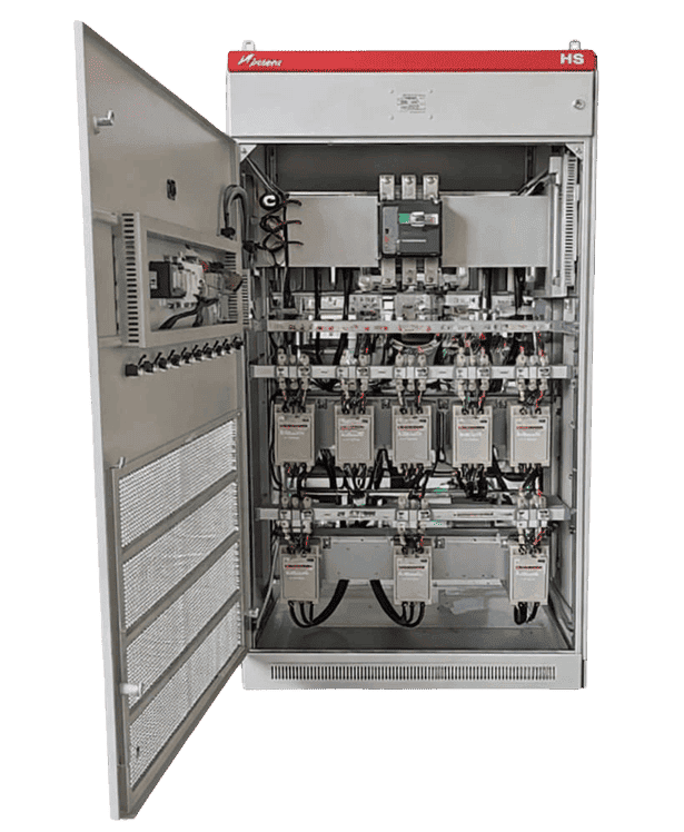
Dynamic Reactive Power Compensation Device
Fast dynamic VAR compensation for rapidly fluctuating industrial loads—designed for stable voltage, PF compliance, and harmonic-stressed environments.
- Compensation response < 20 ms (system)
- Thyristor switch response < 5 ms
- Designed for medium / heavy harmonic industrial environments
If this is your day-to-day, our solution is built for it
Where This Solution Fits Best
Load swings that hit hard
When production runs on frequent starts, stops, and mode changes, power factor doesn’t slowly drift—it drops in sharp steps. INPTSC is built for these repeatable “swing moments,” helping the system recover quickly each time the load state changes.
Harmonic-Heavy Workshops
If your site runs lots of drives and nonlinear equipment, “reactive power only” solutions often feel incomplete. INPTSC is designed for industrial environments with medium-to-heavy harmonics—so it doesn’t just chase power factor, it also helps relieve harmonic stress through dedicated filter branches
Fast correction without over-engineering
Some plants don’t have one single load pattern—they have many, all sharing one LV bus. INPTSC works especially well when reactive demand changes in steps and repeats in cycles, letting staged correction match how your facility actually operates.
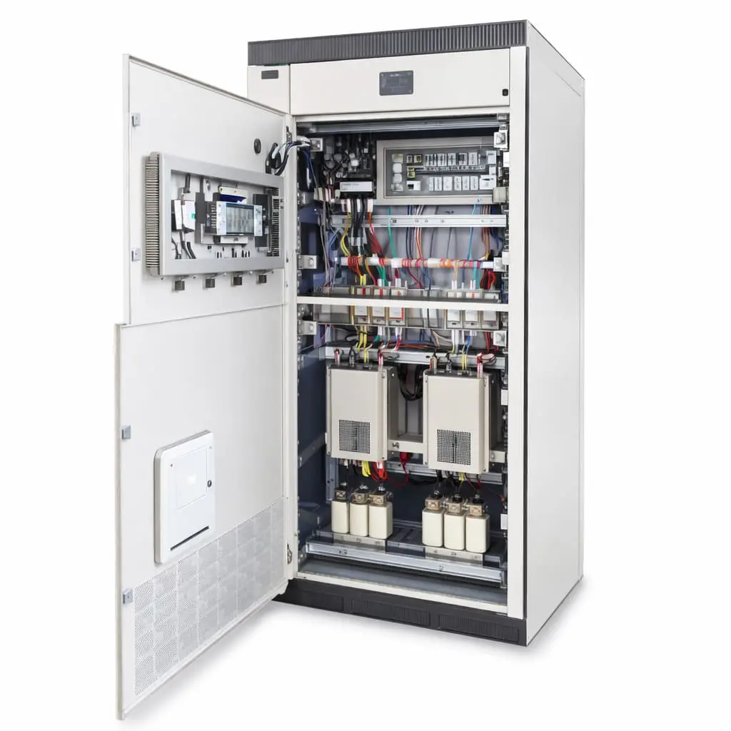
How It Works
Dynamic VAR Compensation Designed for Harmonic-Stressed LV Networks
The operating principle is to deliver dynamic reactive power compensation through solid-state switching that synchronizes with the waveform, enabling rapid output adjustment while keeping the bus free from inrush-driven disturbances. Instead of relying on slow mechanical devices, the thyristor switching architecture allows the compensation capacity to track changing load conditions smoothly at a system level, helping maintain the desired power factor and improving overall power quality in real operating scenarios. Where harmonics are present, the compensation is implemented through filter-capable branch structures using capacitors and series reactors (commonly 7%/14% detuning) to support stable operation and reduce the risk of harmonic amplification.
From Disturbance to Stability: Power Quality Solutions
How We Resolve Power Quality Challenges
Stop Voltage Flicker During Rapid Load Shifts
Fast dynamic compensation stabilizes reactive demand so bus voltage stays steady, protecting drives, PLCs, and sensitive instrumentation during process cycling at every operating point.
Eliminate Power Factor Drops at Peak Demand
Real-time kvar tracking maintains a stable power factor target, reducing penalties and preserving usable capacity for existing transformers, switchgear, and feeders throughout production runs.
Reduce Harmonic Current Stress on Upstream Equipment
Engineered filter branches limit harmonic interaction, lowering heating and resonance risk in cables, capacitors, and transformers while improving overall current waveform on busy buses.
Control Three-Phase Unbalance and Neutral Overload Risks
Balanced phase control corrects unbalance and reduces neutral current, improving voltage symmetry and avoiding single-phase overload on transformers and feeders under uneven load mixes.
Six Reasons Engineers Choose It
What Makes This Solution Different
Zero-Cross Switching, No Inrush
Thyristor zero-cross switching eliminates capacitor inrush, reducing switching stress and nuisance trips in high-cycle operations.
Millisecond-Level Dynamic Response
Fast control and switching deliver total response within 20ms, supporting rapidly changing loads and process stability.
Built for Harsh Harmonic Sites
Optimized for heavy harmonic environments and fluctuating industrial loads, ensuring stable compensation under nonlinear conditions.
Flexible Compensation Topologies
Supports three-phase, single-phase, and mixed compensation schemes to match site wiring realities and load profiles.
Verified Harmonic Mitigation
Filter branches combine capacitors with 7%/14% series reactors to reduce resonance risk and improve harmonic tolerance.
High-Capacity Branch Scalability
Single branch capacity can reach 450kvar, enabling practical scaling for large low-voltage reactive compensation needs.
Technical Specifications
Category | Specification | Parameter |
|---|---|---|
Electrical Characteristics | Rated voltage | 400V / 690V (Other voltage levels customizable) |
Control Voltage | 220V AC | |
Measurement voltage | 5V ~ 1500V AC | |
Measurement Current | 0.05A ~ 5A AC | |
Wiring Mode | 3P3W or 3P4W | |
Compensation Capability | Full response time | ≤ 20ms |
Module installation method | ≤ 5ms | |
Switching technology | Thyristor zero-cross switching | |
Max system voltage level | Up to 690V | |
Max single-circuit capacity | Up to 450 kvar | |
Compensation modes | 3-phase common compensation / single-phase compensation / hybrid (single-phase + common) compensation | |
Capacitor type & overcurrent | Dry-type, self-healing, built-in pressure protection filter capacitor; overcurrent 2In | |
Compensation loop components | Closed-core magnetic circuit structure; no RF interference; reactance rate 7% or 14% | |
Filter circuit design principle | Designed according to characteristic harmonics | |
Mechanical, enclosure & installation environment | Overall dimensions (W×D×H) | 800×800×2200 / 1000×1000×2200 (Other sizes customizable) |
Protection rating | IP20 (Other IP ratings customizable) | |
Operating condition | 2000 m, -25°C to +45°C | |
Environmental requirements | No severe vibration/impact; no conductive or explosive dust; no corrosive gases |
Let’s Fix the Root Cause—Not Just the Symptoms
Ready to Optimize Your Power Quality?
If harmonics, PF penalties, or nuisance trips are affecting uptime, let’s fix the root cause. Send your site conditions and we’ll map the right correction approach for stable, measurable results.