System-level correction Solution for LV distribution
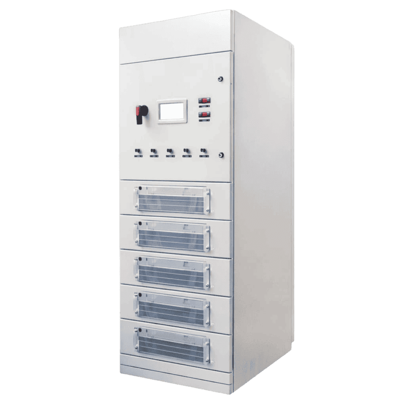
Hybrid Dynamic Filter Compensation System
Cabinetized power-quality correction solution built for industrial LV distribution: A cost-efficient hybrid approach that avoids oversizing a single technology—fast dynamic compensation, controlled harmonics, and low operating loss in one integration-ready system.
- ≤ 5 ms dynamic response
- ≤ 1% reactive compensation accuracy
- Up to 90% single-harmonic filtering rate
- < 2% system loss
Where This Solution Fits Best
Ideal when a single device can’t cover the full power-quality picture and you need coordinated filtering and compensation in one cabinet.
Separate Devices Won’t Stay Coordinated
When filtering and compensation are installed as separate boxes, they can compete or drift with different settings and response behavior. This integrated system uses one control strategy to align harmonic filtering, dynamic VAR support, and switched capacity.
Step Compensation Can’t Hold the Target
Capacitor-step correction is cost-effective, but it can’t maintain stable PF under rapid load changes—especially when harmonics are present. This system keeps PF and VAR targets steady by combining fast electronic correction with switched kvar support.
Harmonic Filtering Alone Leaves PF Problems
Reducing harmonics doesn’t automatically fix low power factor or voltage instability caused by reactive swings. This system filters harmonic current while also correcting reactive power dynamically, keeping overall power quality within defined targets.
How It Works
Integrated power quality compensation solution for complex low-voltage buses
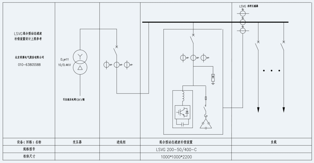
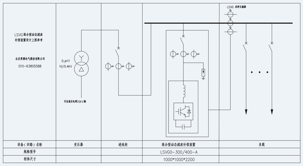
The Hybrid Dynamic Filter & Compensation System is an integrated low-voltage power quality solution developed with advanced power-electronic control. It integrates Active Power Filter (APF), Static VAR Generator (SVG), and Static VAR Compensator (SVC) capabilities in one coordinated cabinet, breaking the limitations of single-scheme solutions by combining active correction with thyristor-switched passive compensation under one intelligent control unit.
Because the system combines active and passive methods, capacity and compensation strategy can be matched to the project rather than forcing a single technology to do everything—supporting a practical balance of performance and total cost. For uptime, it includes comprehensive protections and an automatic fault-tolerant mechanism that can keep the bus supported even if a module or branch is taken out of service.
LSVG vs APF vs SVG vs SVC — Comparison Table
Item | APF (Active Power Filter) | SVG (Low-Voltage Static VAR Generator) | SVC (Low-Voltage Static VAR Compensator) | LSVG (Hybrid Compensation System) |
|---|---|---|---|---|
What it is | Active filter that injects compensation current to cancel harmonics (and can prioritize harmonic/reactive per settings). | IGBT-based converter that dynamically generates /absorbs reactive power; can also compensate harmonic & unbalance (modes can be combined). | thyristor-switched reactive branches using zero-cross switching (zero-voltage on / zero-current off) for fast switching without inrush/impact. | Integrated cabinet system built from APF + SVG + SVC, coordinated by one ECU; active + passive combined. |
Core job | Remove harmonics (and can do VAR/unbalance within capacity). | Fast dynamic VAR / PF control (can also do unbalance /harmonic modes). | Bulk VAR in steps via thyristor switching (economical kvar). | One cabinet to handle harmonics + VAR swings by coordinating APF+SVG+SVC. |
Best when | Harmonics are the main pain (VFDs/rectifiers, etc.). | PF fluctuates fast; need continuous compensation | PF correction dominates; step control is acceptable; need low cost/kvar. | Plant has both harmonics and fast VAR changes; wants best ROI. |
Typical install point | LV switchboard / PCC / feeder near disturbance source; CT can be load or grid side. | close to the harmonic source feeder or at PCC depending on whether you target local or whole-bus THDi. | often at PCC or load bus where PF fluctuates most. | usually in compensation cabinet on LV bus, paired with capacitor/reactor branches. |
Speed | ≤5 ms | ≤5 ms. | Fast switching (zero-cross), but step-based compensation. | ≤5 ms (system), with coordinated control; whole-set dynamic behavior described. |
Capability highlight | Supports PF from -1 to 1 reactive compensation; can choose modes (constant VAR / constant PF). | PF control with fine, fast dynamic VAR; supports capacitor switching control (“capacitor coarse + SVG fine”). | Step/branch-based reactive compensation via thyristor switching; optimized for fast safe switching with minimal disturbance | Uses ECU targets (VAR/voltage/PF/harmonic removal rate) to decide switching and coordinate modules; reactive compensation accuracy ≤1% |
Main advantage | Strong harmonic range (up to 51st), high target harmonic filtering, fast response; also supports reactive and unbalance functions. | Continuous dynamic VAR control; fast response; modular parallel operation; multi-mode capability; good efficiency. | Cost-effective bulk VAR; thyristor zero-cross switching reduces inrush/impact; fast step switching. | Hybrid economics + system intelligence + fault tolerance: combines active (APF/SVG) + passive (SVC) under one ECU to reduce cost while achieving “best compensation + filtering effect.” |
Best-fit scenarios | When harmonics dominate (e.g., high THDi), and you want high-order harmonic mitigation with fast response. | When reactive power fluctuation is the main pain (PF penalties, voltage dips from inductive swings) and you also need unbalance/harmonic modes. | When you need economical bulk kvar (steady reactive compensation) and switching quality matters (no inrush/impact). | When you must solve PF + harmonics + fast load swings together and want a coordinated, cost-optimized system with resilience |
From Disturbance to Stability: Power Quality Solutions
How We Resolve Power Quality Challenges
Reduce Harmonic Distortion
When drives and rectifiers push distortion into the bus, equipment runs hotter and protection trips increase. We reduce harmonic impact so current stays cleaner and more stable.
Stabilize Power Factor
Reactive demand swings during starts and process cycles, causing penalties and voltage stress. We keep power factor and VAR demand controlled so the bus stays within targets
Correct Phase Imbalance
Uneven phase loading drives neutral current and wasted capacity, especially on mixed single-phase loads. We improve phase balance to reduce losses and stabilize distribution performance.
Support Bus Stability
Power quality problems often spike during load transitions, not steady state. We maintain predictable bus conditions through change events to protect uptime and sensitive equipment.
Six Reasons Engineers Choose It
What Makes This Solution Different
FPGA-Based Control Core
A single controller coordinates APF, SVG, and SVC so filtering and compensation act as one system—not separate devices with competing logic. Control decisions follow target values for VAR, voltage, power factor, and harmonic removal rate.
Hybrid Architecture Done Right
Active correction (APF/SVG) is combined with switched capacity (SVC) in one package, and the active side can also command the passive side when needed. This achieves strong performance without forcing one technology to do every job.
Fast Dynamic Correction
The system tracks load changes in real time, with <5 ms full response per functional unit and <20 ms full-system response for dynamic dispatch and switching. This helps keep power quality stable during starts, steps, and process cycling.
High-Order Harmonic Governance
It supports practical harmonic governance with a stated single-harmonic removal rate up to 90%, and the APF module supports filtering up to the 51st harmonic with 97% effective filtering of target harmonics within capacity.
Precision Reactive Compensation
Reactive compensation is specified at ≤1% accuracy, supporting stable power factor control without chronic over- or under-compensation. This is built for plants that need repeatable PF performance as loading changes.
Automatic Fault-Tolerant Operation
An automatic fault-tolerant mechanism is defined: if the SVG section faults, the system can switch to SVC+APF operation; if an SVC branch faults, it can be removed from the switching sequence. This protects uptime and reduces recovery time.
Technical Specifications
Category | Specification | Parameter |
|---|---|---|
Electrical Characteristics | Rated input voltage | 380 V |
Input voltage range | 304 V ~ 456 V | |
Input voltage unbalance | ≤ 5% | |
Wiring Mode | 3-phase 3-wire or 3-phase 4-wire | |
Harmonic filtering performance | Single harmonic removal rate: 90% | |
Compensation Capability | Dynamics Response time | ≤ 5 ms |
Full-system respons | Each functional unit < 5 ms; system full response < 20 ms | |
Measurement | Electrical parameters measured/displayed | 3-phase voltage, 3-phase current, active power, reactive power, power factor |
Protection | Safety & protection functions | Over/under-voltage, overcurrent, over-temperature, phase loss; voltage/current harmonic limit protection; interlock alarm; fault info data storage |
Cooling | Cooling method | Intelligent forced-air cooling |
Mechanical | Structure | Cabinet type |
Enclosure protection rating | IP30 (customizable for special requirements) | |
System Efficiency | Power consumption / loss | < 2% |
Compensation | Reactive compensation accuracy | ≤ 1% |
Acoustic | Noise | < 60 dB |
Environment | Ambient temperature | -15°C to +40°C |
Daily average temperature | ≤ 35°C | |
Relative humidity | 15% ~ 90% RH (at 20°C) | |
Altitude | < 2000 m | |
compatibility | Cabinet compatibility | Compatible with multiple cabinet types; customizable |
Engineering note | Recommended max cabinet capacity | Max capacity per cabinet is generally not recommended to exceed 400 kvar; >400 kvar uses two cabinets |
Ready to Improve Your MV Power Factor?
Get an MV Compensation Plan Built for Your Bus
Whether you operate a public distribution network or an industrial MV system, we’ll help you select the appropriate solution. Provide your measured PF/reactive data and operating profile. We’ll return a clear recommendation that improves MV bus performance, simplifies operation, and supports stable, repeatable compensation results.