Dynamic conditioning for harsh harmonic conditions
Active Harmonic Filter
Real-time harmonic cancellation for nonlinear industrial loads—designed to reduce THD, relieve harmonic-driven losses, improve system stability, and trouble-free operation under changing load conditions.
- Filters harmonics up to the 51st order
- ≤ 5 ms response for fast-changing loads
- Target harmonic filtering effectiveness up to 97%
- Built for harsh transients: 2.5× / 10 ms overload
Where This Solution Fits Best
If these symptoms show up in your power system, you’re in the right place.
Sensitive Loads Misbehave
Sensitive equipment behaves inconsistently—drives hunting, UPS warnings, PLC glitches, or measurement drift. The site feels “electrically noisy,” and fixes tend to be temporary or device-specific.
Overheating in Power Gear
Transformers, cables, and switchgear heat up faster than expected, even when loading looks “normal.” You may see insulation aging, odor, or repeated temperature alarms during peak production.
Unexplained Trips & Resets
Breakers, drives, or protection relays trip without a clear root cause, especially when multiple nonlinear loads operate together. The issues are intermittent, hard to reproduce, and costly in downtime.
How It Works
Real-time compensation current that neutralizes harmonics at the source
Three-Level APF Design for Stable, High-Quality Compensation
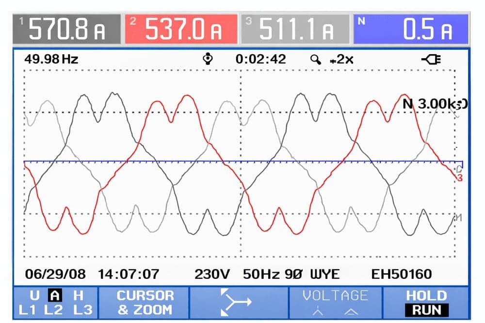
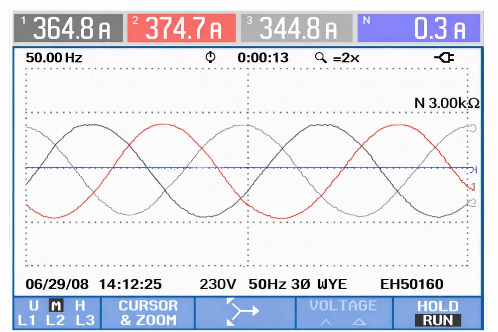
Our Active Harmonic Filter is engineered around one goal: deliver predictable harmonic and reactive power correction even when loads fluctuate. Its control system continuously tracks distortion in real time and commands the power stage to inject compensation current instantly—maintaining stable performance as operating conditions shift. Built on a three-level inverter topology, our solution synthesizes compensation current more smoothly, helping reduce ripple and electrical stress. With flexible CT placement and configurable priority between harmonic filtering and reactive support, the system adapts to site realities—so you achieve compliant power quality without redesigning your distribution system.
Cleaner waveforms for harsh loads
How We Resolve Power Quality Challenges
Reduce Harmonic Distortion, stop Overheating Issues
Reduce THDi at the bus so transformers, cables, and generators run cooler with fewer alarms and less derating overall during operation.
Restore Power Factor Stability Under Dynamic Loads
Keep power factor on target as loads swing, cutting reactive penalties and preventing voltage dips that disrupt motors and drives.
Improve Phase Balance & Neutral Current Conditions
Balance phase currents to lower neutral overheating, reduce single-phase overload risk, and stabilize protection settings across mixed, uneven loads sites.
Prevent System-Level Amplification & Resonance Risks
Address harmonic interactions that can magnify distortion in distribution networks, lowering the likelihood of cascading power-quality problems.
Six Reasons Engineers Choose It
What Makes This Solution Different
Three-Level Topology
Three-level topology enables finer output synthesis with smoother compensation current, supporting consistent correction quality under dynamic conditions.
Wide Harmonic Range
Targets 2–51st harmonic mitigation with adjustable orders and ratios—so you can tailor correction to real load spectra, not generic defaults.
≤5 ms Fast Correction
Delivers dynamic compensation with ≤5 ms response—supporting stable correction even when distortion levels and load conditions change rapidly.
Up to 97% Effective Filtering
Within rated capacity, filtering effectiveness can reach up to 97% on targeted harmonics—helping you achieve predictable results under defined operating limits.
Multi-Mode Control
Supports harmonic filtering, reactive compensation, and unbalance correction—enabling one platform to address multiple root causes on the same LV bus.
Overload Margin
With 1.2×/1 min and 2.5×/10 ms overload tolerance, the system is better equipped to withstand short transients without losing correction continuity.
Technical Specification Sheet
Category | Item | Specification |
|---|---|---|
Electrical & Performance Parameters | Rated compensation current | 50A / 80A / 100A / 120A / 150A / 100A |
Rated overload capability | 1.2 × rated current / 1 min; 2.5 × rated current / 10 ms | |
Wiring method | Under AC380V: 3P4W (3P3W customizable); Under AC690V: 3P3W | |
Rated operating voltage | AC380V ±20%; AC690V ±15% | |
Rated operating frequency | 50 Hz /60 Hz (±10%) | |
Response time | ≤ 5 ms | |
Harmonic filtering range | 2nd–51st order | |
Harmonic filtering capability (within capacity) | Up to 51st harmonic; effective filtering on target harmonics up to 97%; filtering order(s) and filtering ratio adjustable | |
Reactive power compensation | Fine compensation with PF range from −1 to +1; modes: Constant VAR mode / Constant PF mode | |
Unbalance compensation | Balances three-phase current; avoids transformer single-phase overload; improves effective capacity utilization | |
Function configuration (priority) | Harmonic compensation / Reactive compensation / Unbalance compensation; free combination with priority setting | |
Compensation modes | 3-phase common compensation / single-phase compensation / hybrid (single-phase + common) compensation | |
System Interface & Communication | Communication | RS-485; Modbus-RTU protocol |
Dry contacts | 1 × input contact: start/stop control; 3 × output contacts: Run / Power / Fault | |
CT installation | CT installation position: supply side / load side; automatic CT phase sequence identification | |
Parallel operation | Supports multi-unit parallel operation; unequal capacity parallel operation supported | |
Power System Connection & Wiring | Overall dimensions (W×D×H) | 800×800×2200 / 1000×1000×2200 (Other sizes customizable) |
Environmental, Cooling & Acoustic | Cooling method | Forced air cooling |
Ambient temperature (operation) | 40°C (rated), max 55°C; automatic derating 2%/K above rated temperature | |
Altitude | ≤ 3000 m | |
Noise level | ≤55 dB; ≤65 dB (depending on model) | |
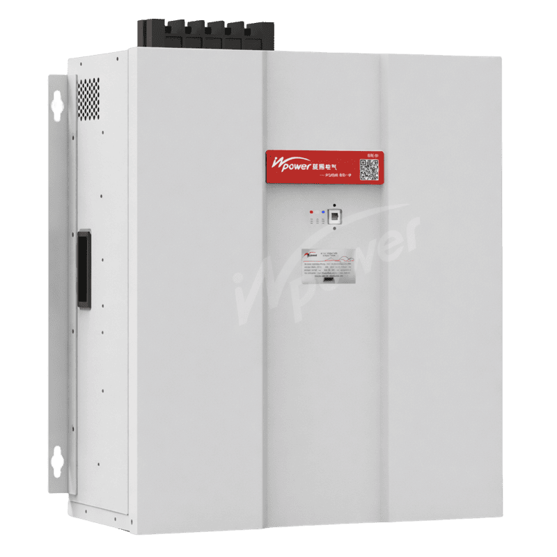
Dimensions (W×D×H, mm) | Wall-mount | 400×190×570; 450×200×620; 480×270×707 |
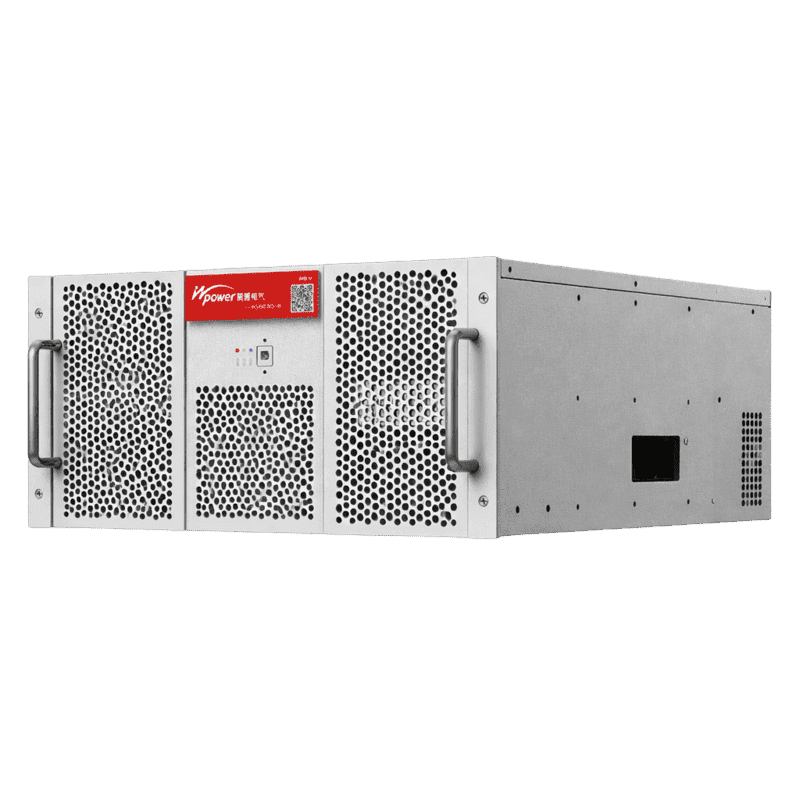
Drawer type | 530×550×190; 530×550×190; 475×600×270; 550×600×270 | |
Ingress protection | IP20 (standard) |
Let’s Fix the Root Cause—Not Just the Symptoms
Ready to Optimize Your Power Quality?
If you’re facing harmonic limits, equipment overheating, or commissioning delays, we can help you reach a stable, verifiable power-quality baseline with the right solution architecture. contact us today, let our engineers will recommend a configuration and quotation tailored to your site conditions.